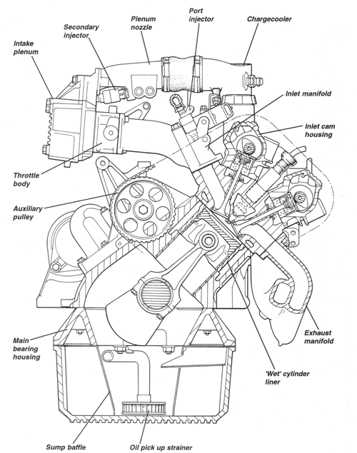
4 Cylinder Engine (907, 910, 912)
Cylinder Block
The die-cast, all alloy, four cylinder engine is inclined at 45° and is
fitted with twin overhead camshafts operating four valves per cylinder in
`pent roof' combustion chambers. The cylinder block uses `wet' cylinder
liners forged from aluminum alloy, with a `Nikasil' coating applied to the
bores. The liners are a push fit into the open deck block and are fitted
with forged aluminum alloy, solid skirt pistons, with nickel or chrome
plated crowns, and two compression and one oil control ring located above
the fully floating gudgeon pin, itself retained by wire circlips. The
cylinder block extends to the horizontal centre line of the crankshaft, with
the lower halves of the main bearings being contained within a one piece
main bearing panel bolted to the bottom of the block. Below this is bolted a
die cast aluminum alloy sump.
Cylinder Head
The cylinder head contains two inlet and two exhaust valves per cylinder,
at an included angle of 38°, and are actuated directly by the camshafts via
inverted bucket tappets and selective `biscuit' shims. The exhaust valves
are sodium filled to assist cooling, and operate in bronze guides, whereas
the solid inlet valves use cast iron valve guides. Each valve is closed by
dual helical valve springs, and seals against a replaceable sintered steel
seat insert in the combustion chamber. A separate camshaft housing for inlet
and exhaust camshafts is fitted on the cylinder head with the five journals
on each camshaft running directly in the housing, with end float controlled
by a selective thrust washer at the rear end.
Crankshaft and Reciprocating Components
The cast iron, dynamically balanced crankshaft runs in five steel backed
leaded bronze lined main bearings, with end float controlled by thrust
washers located in the cylinder block on either side of the rearmost main
bearing. A steel flywheel, bolted to the crankshaft rear flange, has an
integral starter ring gear machined on its periphery. The I-section forged
steel connecting rods have steel backed bronze lined big end bearings, with
the bearing caps located by dowels and retained by bolts.
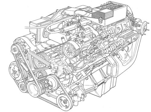
Camshaft Drive and Valvegear
An auxiliary shaft is mounted on the right hand side of the crankcase in
a separate auxiliary housing onto the rear of which is fitted a trochoid
type oil pump, and a flexible impeller type chargecooler water pump. Both
camshafts and the auxiliary shaft are driven from the front end of the
crankshaft by a single toothed rubber belt, provided with a manually
adjusted eccentric belt tensioner.
Lubrication
The wet sump lubrication system uses a trochoid type oil pump mounted on
the rear of the auxiliary housing on the right hand side of the cylinder
block. The pump is driven by the auxiliary shaft which is itself driven via
toothed pulley from the camshaft drive belt.
Oil is stored in a cast aluminum sump fitted with sheet steel baffles, and is drawn through a gauze screen, up a pick-up pipe into the auxiliary housing, and into the inlet side of the oil pump. The pump uses a 6-lobe rotor keyed to the auxiliary shaft, and turning within a 7-lobe annulus housed eccentrically in the pump body. The space between the rotor tips and annulus expands and contracts as the components rotate, causing a depression at the pump inlet port, and pressurizing the oil at the pump outlet, where a spring plunger type pressure relief valve incorporated into the body of the pump, bleeds off excessive pressure back to the inlet side of the pump.
Pressurized oil then flows through a duct in the auxiliary housing to the oil cooler adapter which diverts all the oil flow down flexible hoses to a pair of oil coolers mounted one each side of the main radiator duct beneath the nose of the car. Oil returning from the cooler flows via the oil cooler adapter to the full flow canister type oil filter mounted on the rear of the auxiliary housing. The oil filter, being horizontally mounted incorporates an anti-flowback valve to prevent oil draining from the filter when the engine is stopped.
From the central outlet of the filter, oil flows into the oil gallery which runs along the right hand side of the cylinder block. Five drillings connect this gallery with the top of each crankshaft main bearing. Crank journals 1,2,4 and 5 are provided with drillings through to their adjacent crankpins for big end lubrication, and are also drilled diametrically across the journal. These journals are fitted with main bearing shells having a hole, to admit the oil supply from the block drilling, and a groove which acts as an oil supply channel to one end of the journal cross-drilling, in order to maintain a continuous oil supply to the big end bearing. The journal cross-drilling allows the lower main bearing shells to be plain (rather than grooved) for greater load capacity. The center main bearing, since it does not feed a big end bearing, has an upper shell which has a hole but no groove.
The connecting rods have a small scallop on each side at the top of the big end eye to provide an oil spray to the underside of the piston to aid piston crown cooling and lubrication of the little end and cylinder walls. At the rear of the oil gallery, a separate cover provides take -offs for the oil pressure gauge transducer, and the turbocharger oil feed hose. An armored flexible hose supplies oil to the turbocharger bearing housing, from the opposite side of which the oil drains via a larger bore armored hose back into the left hand side of the sump.
The front end of the oil gallery is extended by a passageway contained by the auxiliary housing, upwards and rearwards, with a drilling supplying oil to the auxiliary shaft front bearing. The auxiliary shaft rear bearing is supplied via a drilling from the oil pump outlet. From the front end of the oil gallery, oil is fed via drillings from the block into the cylinder head where it emerges at each camshaft front bearing. Each camshaft is bored throughout its length to distribute oil to each of its journals, after which the now unpressurized oil, lubricates the cam followers and valve stems on its way, via passageways in the head and block, back to the sump.
Precautions
i) Use only those lubricants listed in section `O' for the ambient temperature range pertaining.
ii) When rebuilding an engine, use copious amounts of recommended lubricant to ensure adequate lubrication on initial start up.
iii) After rebuild, the engine should be cranked with the ignition disabled until oil pressure is registered on the gauge.
iv) If the engine is not to be used for some time after building, the use of a graphogen grease assembly compound (e.g. 'Cylesso' - part no A907E6178V) is recommended for the main and big end bearings. v) Since the oil pump is not of the submerged type, the integrity of the suction pick up side is crucial to oil pump performance, particularly during start up. The nylon olive sealing the pick up pipe into the block should be replaced each time it is disturbed, together with the pick up pipe if heavily `necked'.
In the event of engine failure involving the possibility of debris entering the lubrication system, it is essential that the following precautions are taken before re-assembly:
a) Clean and inspect all engine oilways in block, crankshaft, cylinder head etc.
b) Clean and inspect oil pump, pick up pipe and strainer and auxiliary housing.
c) Thoroughly flush out oil cooler hoses.
d) In view of the difficulty of ensuring no debris is retained in the oil cooler, this item should always be replaced in such circumstances.
Oil Level Checking
Ensure that the car is parked on a level surface and that
a few minutes have elapsed since stopping the engine to allow oil to drain
back into the sump. If the engine is stopped before reaching normal running
temperature, the oil will not drain back to the sump so readily, and the
dipstick will display an artificially low reading.
Dipstick
The dipstick is located at the right hand rear of the engine, adjacent to the intake plenum chamber. Withdraw the dipstick, and wipe with a paper towel. Replace the dipstick, pressing firmly to make sure it is fully seated, and withdraw again to inspect the oil level. The correct level is to the upper mark on the dipstick. Topping Up: If topping up is necessary, remove the oil filler cap at the front of the inlet cam cover, and add a suitable quantity of a recommended engine oil (see `Recommended Lubricants'). Take care not to spill any oil onto the drive belts at the front of the engine, or onto any electrical components; use a funnel if necessary. The difference between high and low dipstick marks is equivalent to 0.85 liter (1.5 imp.pt; 0.9 US qt). Allow several minutes for the oil to drain through to the sump before rechecking the oil level. Do NOT overfill, or the oil will become aerated and its lubricating properties degraded. Refit the filler cap and turn clockwise until the ratchet mechanism is heard to 'click' indicating that the cap is fully tightened.