Installing a Raid Airbag Wheel
by Jim Knowles
Tools required
Note that all of the airbag wiring in the following pictures are yellow and marked as SIR (Supplementary Inflatable Restraint) circuits.
*Before beginning be sure to note how the stock steering wheel is aligned with the wheels tracking straight ahead. If for some reason your steering wheel is not straight up/down when the car is going straight ahead you may be able to correct that when mounting the new wheel.
Also, be sure to do your yoga exercises in preparation for assuming Lotus position #1 (head in footwell, feet on the roof) as this will be required for steps 1 and 2
Procedure
Step 1
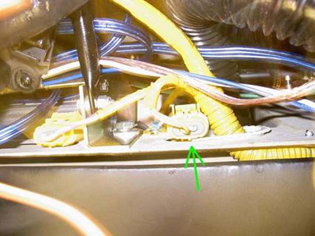
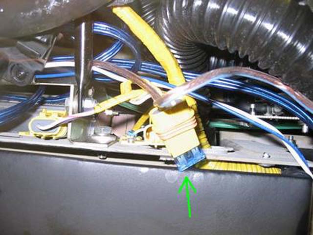
Locate the 15 amp fuse holder for the airbag circuit in the passenger side footwell just behind the dash cover and remove the fuse. It is the one closest to the center console. See Photos A and B
Photo A
Photo B
Step 2
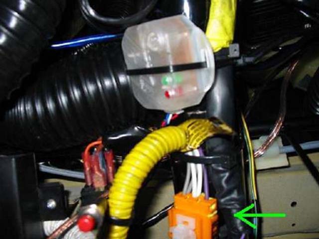
Locate the driver’s side airbag harness connector attached to the steering column and unplug the harness. See Photo C
Photo C
Step 3
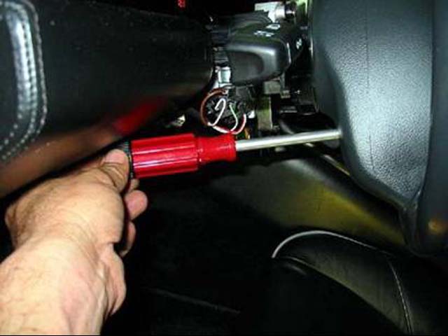
Loosen the four (two on each side) T25 torx screws at the back of the steering wheel which attach the airbag assembly to the steering wheel. These are captured screws and will not come out completely. Do one side at a time and alternately loosen each screw a few turns until they are both completely released and then do the other side. You will have to rotate the steering wheel to allow access for your torx driver. See Photo D
Photo D
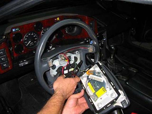
Step 4
You may now carefully remove the center airbag portion of the wheel. You will see two connectors inside the wheel. The one connecting the airbag circuit and the other is for the horn circuit. Cut the two wires going from the steering column to the airbag connector leaving the entire connector attached to the airbag with enough wire on the airbag side in case you ever want to re-install the factory wheel. Be sure to leave enough on the steering column side to splice in the new connector. See Photo E
Photo E
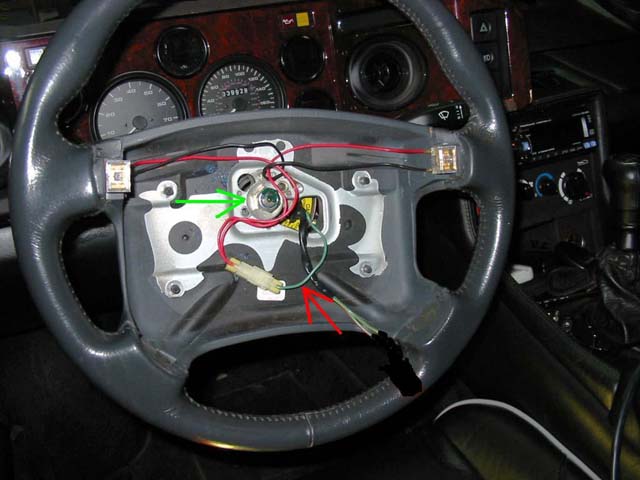
Step 5
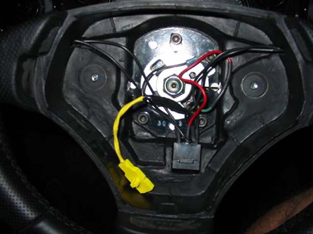
*Center the steering wheel to the straight ahead position as noted in the beginning. Remove the 19mm nut in the center of the steering wheel. (green arrow in Photo F)
Cut the horn wire (red arrow in Photo F) between where it comes through the steering wheel and the connector, being sure to leave enough wire on both sides as you did in Step 4.
Photo F
With your hands gripping the wheel at the 3 o’clock and 9 o’clock positions, rock the wheel back and forth while pulling on the wheel and it should pop loose and come off. You are not turning the wheel, just rocking it with your hands. (only use minimum force, do not try to rip it off like a gorilla) Be sure to keep the steering column shaft oriented straight when the wheel comes off the column in order to correctly align the new wheel.
If for some reason it doesn’t come loose with minimal force you will then need to resort to some kind of wheel puller.
As per the Lotus Service Notes-- CAUTION: Do NOT apply excessive axial force to the column without the use of a steering wheel puller or the mechanism retaining the telescopic length of the collapsible column may be overridden, necessitating column replacement.
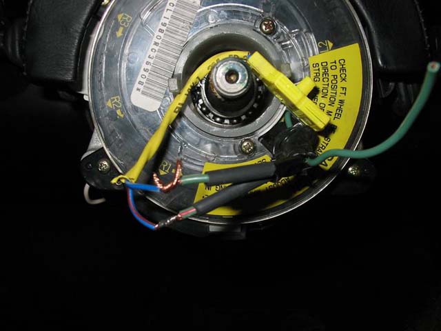
Once the wheel is off you should be careful not to rotate the plastic rotary connector too far since it needs to stay in this orientation when the new adapter is installed. The rotary connector and the two plastic pins protruding from it are what supplies power to the horn/airbag and cancels the turn signal when the wheel is turned.
Step 6
Splice the supplied airbag connector to the two wires that you cut in step 4. It doesn’t matter which wire goes to which, just be sure the two connections are insulated from each other. I prefer to solder the connections and use heat shrink tubing (also supplied) to insulate each connection and then use more heat shrink or electrical tape over the entire splice. The photo shows one connection soldered and the other partially twisted in preparation for soldering. Don’t forget to put the heat shrink tubing over the wire before you twist them together. See Photo G.
Photo G
Step 7
Splice the red wire with the female spade connector on one end (supplied) to the green horn wire from the column and be sure the connection is insulated against any possible metal contact.
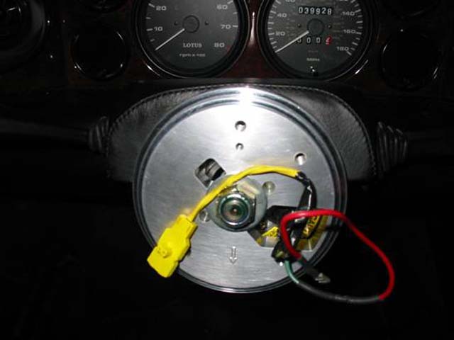
Step 8
Install the custom machined adapter with the arrow side out and with the arrow pointing straight down. The large opening should be to the right and the wires (horn/airbag) from the rotary connector on the column go through this opening. Slide the adapter gently onto the shaft and once the splines are engaged align the two plastic pins on the rotary connector with the appropriate holes on the adapter and push the adapter completely onto the shaft. Finger tighten the 19mm nut on the shaft to hold the adapter in place.
Using the small M4 screw (supplied) secure the black horn ground wire with the ring connector (supplied) to the 4mm threaded hole in the adapter. See Photo H
Photo H
Step 9
Remove the airbag from the Raid wheel and install your new steering wheel to the mounted adapter using the four M6 allen screws supplied. Tighten securely but do not over tighten as the threads on the adapter can be stripped with too much torque.
Now tighten the 19mm steering column nut and torque to 40Nm (30 ft. lbs)
Plug the red horn wire with female spade connector into the appropriate terminal on the wiring block of the steering wheel. Plug the black ground wire with female spade connector into the remaining terminal of the wiring block. See Photo I.
Photo I
At this point you may drive the car if you wish to make sure the steering wheel is centered correctly and because by this time you won’t be able to wait any longer to see just how great the new steering wheel feels. You will also notice we have enlarged the interior of the car by about 23.445% or at least it feels that way.
If you turn on the ignition your airbag warning light should be on at this time and if it’s not you have a problem since we have not yet connected it.
If after test driving the wheel is not centered correctly, note its’ location when tracking straight ahead so you can duplicate that steering wheel position when you get back in the garage. If adjustment is needed, remove the 19mm nut and pull the entire wheel/adapter assembly and rotate right or left to the correct orientation.
Step 10
After determining all is well with the wheel orientation, connect the airbag electrical connector to the new airbag and install the airbag in place being sure that all the exposed wiring is securely tucked/taped into the recess in the center of the wheel. Tighten the torx screws to secure the airbag.
Step 11
Reconnect the airbag harness connector on the steering column from Step 2 and then replace the 15 amp fuse removed in Step 1. Check the horn button to confirm the horn works.
As per the Lotus Service Notes
Conduct the “SIR Diagnostic System Check” as follows:
Turn on the ignition and observe the SIR tell tale; it should flash
seven to nine times and then go out. When the engine is cranked, the
lamp should come on steady, and then flash for another seven to nine
times after the engine has started.
WARNING: If the SIR tell tale lamp does not come on with the ignition, and follow the sequence above, or if it lights at any other time, a fault in the SIR system is indicated which should be investigated without delay (see section WC.4 of the SIR Service Notes) as the SIR may not function correctly
Install is complete, go out for a spirited drive and enjoy your new steering wheel.